Published by NST on the Feb. 18, 2025, 4:20 p.m. view all posts
Designing a processor from scratch, how hard can it be?

Whether it’s GPUs, ASICs, FPGAs, embedded systems, or any other kind of low-level hardware, I figured that understanding how processors work at a fundamental level is crucial for debugging. Tackling performance bottlenecks in software also benefits from this knowledge. It translates into more effective and informed decision-making in design. It’s also pretty interesting to see how different modules work together at a low level abstraction and gives you a deeper appreciation for the complexity of high-performance processors.
This project is meant to be simple (kind of... haha) and for students/hobbyists. I coded it using Verilog, implementing a simple processor (top) with an ALU (Arithmetic Logic Unit), control unit, and register file. This processor also follows the basic principles of RISC.
Key Concepts in Processor Design
1. The Processor: The Brain of the System
The processor coordinates all operations. It fetches instructions, decodes them, and executes the required computations using different components like the ALU, register file, and control unit.
2. The ALU (Arithmetic Logic Unit): Performing Operations
The ALU is responsible for executing arithmetic and logic operations. It receives inputs, processes them according to an opcode, and outputs a result.
How it works:
-
The processor sends necessary data to the ALU: inputs a, b, and the opcode (which determines the operation).
-
The ALU performs the operation based on the opcode:
-
000000→ Addition (a + b) -
000001→ Subtraction (a - b) -
000010→ Bitwise AND (a & b) -
000011→ Bitwise OR (a | b)
-
-
The result is sent back to the processor and assigned to the result output.
3. The Register File: Storing and Retrieving Data
The register file stores values that the processor and ALU use during execution.
How it works:
-
The control unit specifies which register to read from.
-
The register file retrieves the data and sends it to the ALU as an input.
-
The result from the ALU can be stored back into the register file if needed.
-
On reset, all registers are cleared to
0.
4. The Control Unit: Directing the Flow
The control unit is responsible for decoding instructions and generating control signals for other components.
How it works:
-
It extracts the opcode from the instruction to determine what operation the ALU should perform.
-
It enables the ALU only when necessary (
alu_enable). -
It determines which register should be accessed (
reg_addr). -
It ensures smooth coordination between the processor, ALU, and register file.
5. How It All Works Together
-
The processor fetches an instruction and sends the necessary control signals.
-
The control unit decodes the instruction, enabling the ALU and specifying the register address.
-
The register file sends the required data to the ALU.
-
The ALU performs the operation and produces the result.
-
The result is assigned to the processor's output.
6. Testbench
I am using VS code for everything and installed iverilog and gtkwave using;
sudo apt install iverilog gtkwave
Writing Verilog is one thing, but making sure the processor actually works under different conditions is another. A good testbench helps catch subtle bugs that may not be obvious just by looking at the code. A processor might work fine for basic cases, but edge cases like handling zero, negative numbers, or maximum values often reveal design flaws. At one point, I had an issue where reg_addr was always stuck at 0. This meant that my processor was always reading from register 0, regardless of the instruction.
For compiling my verilog I ran;
iverilog -o testbench/processor_tb.vvp src/processor.v src/alu.v src/reg_file.v src/control_unit.v testbench/processor_tb.v
To view the waveform simply run (or whatever you gave the name for your vcd dumpfile in the testbench);
gtkwave processor_waveform.vcd
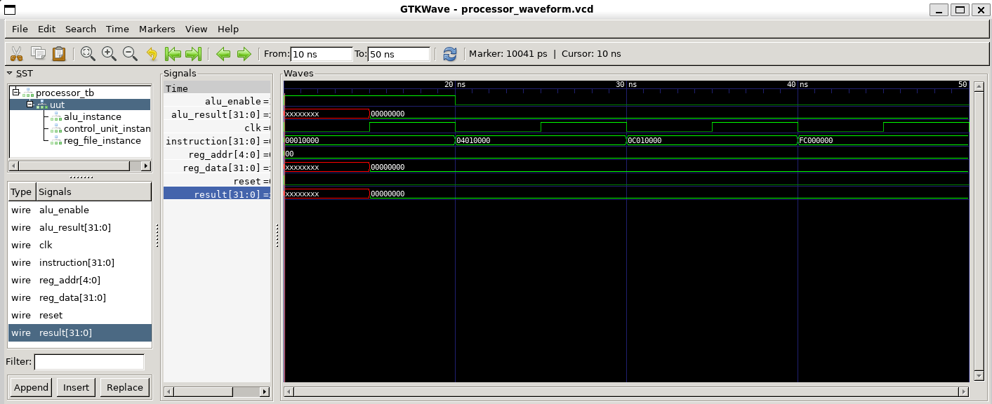
Debugging the waveform revealed that the control unit wasn't correctly decoding the instruction and updating reg_addr. The fix involved properly extracting the correct bits from the instruction and ensuring the control signals were being assigned correctly. Easy to spot in a simple 32-bit processor, simulation was fairly fast, not nearly as complex as a full-blown CPU with pipelining, caches, or branch.
Link for the Verilog code and a simple testbench below:
https://github.com/nanosilica/processor_flow.git
This is an ongoing project. To be continued...
Comments...
André Powell - Feb. 18, 2025, 9:51 p.m.
I will have a look at this :). I knocked up Noddy which also was simple to keep up my Verilog skills.